How to Use Tooltrace
Complete guide to creating perfect tool inserts for Gridfinity bins and shadowbox foam.
Getting Started
Tooltrace makes it easy to create custom inserts for your tools. Here's the basic workflow:
Upload Your Photo
Select the Paper
Select Your Tools
Configure Settings
Export
Interactive Tutorial
Practice the basic workflow with this interactive tutorial. Click through the steps to learn how to select paper and trace tools.
Learn Tooltrace
Follow this quick tutorial to learn how to create tool outlines
View full documentationTaking Photos
The quality of your photo directly affects the accuracy of your tool traces. Follow these guidelines for best results.
Understanding Parallax Error
When you take a photo from too close, the camera "sees over" the edges of taller tools, creating an oversized trace. This is called parallax error.
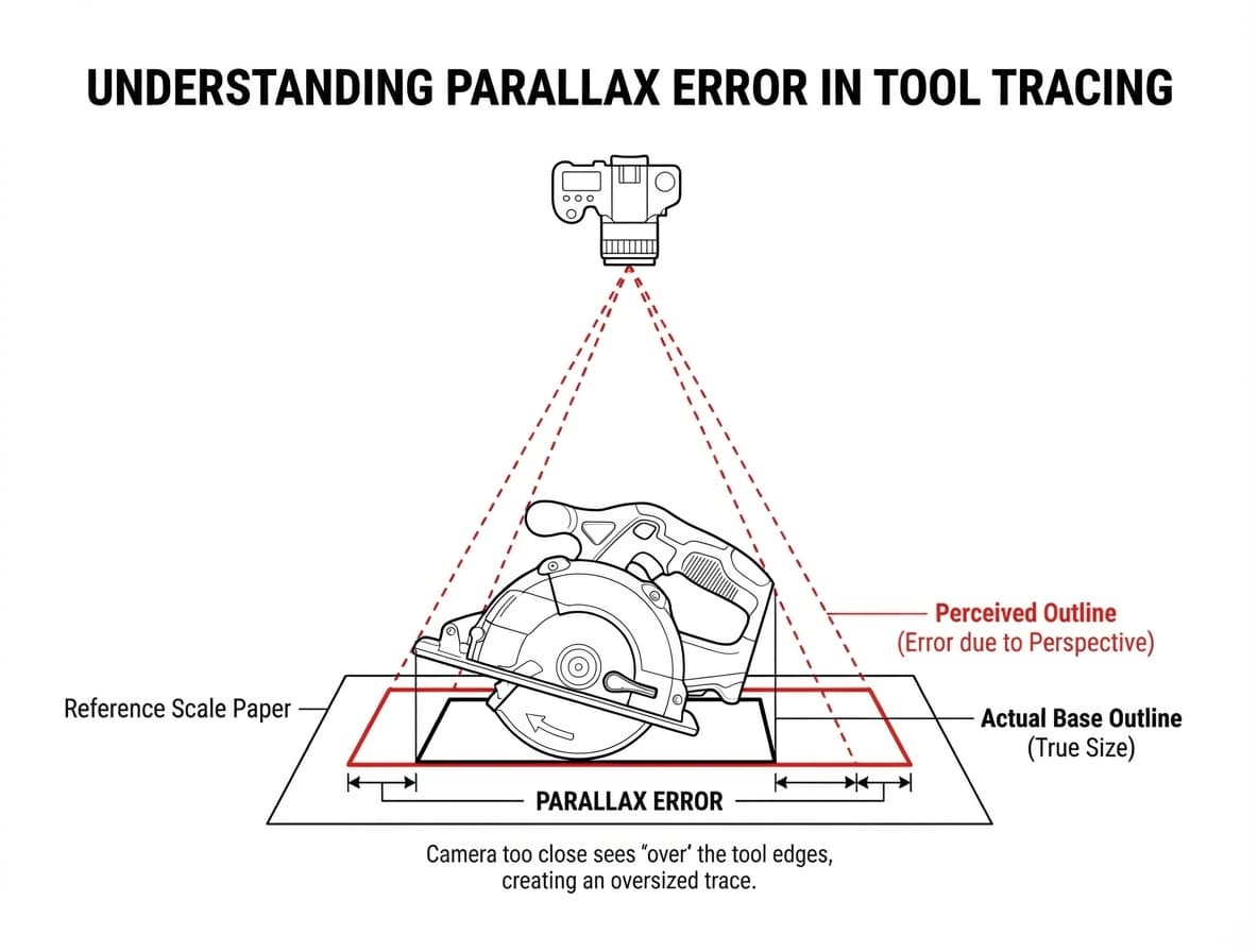
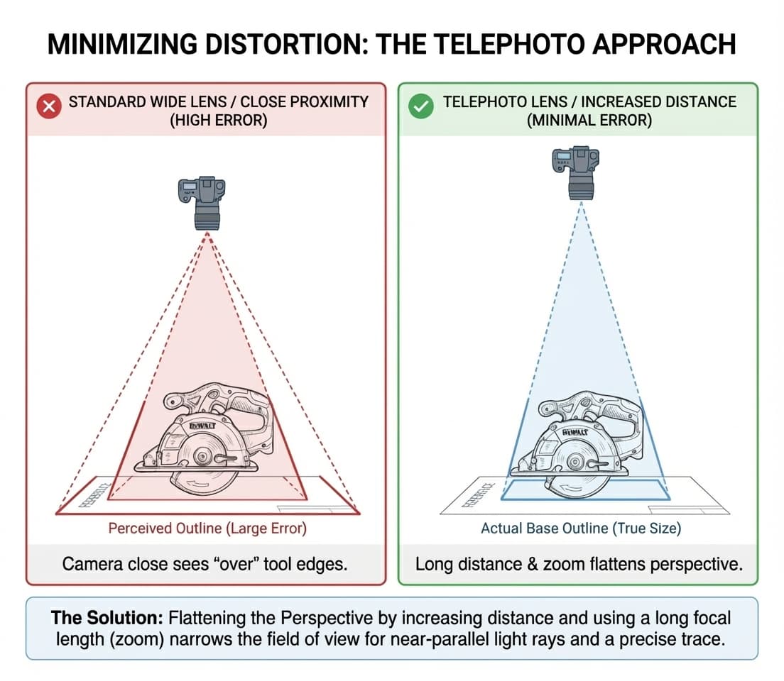
The Solution: Telephoto Approach
To minimize distortion, increase your distance from the tools and use optical zoom (if available). This flattens the perspective and produces more accurate traces.
Recommended Workflow
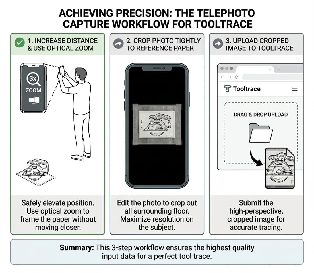
Increase Distance
Stand back and use optical zoom to frame the paper without moving closer.
Crop Tightly
Edit the photo to crop out surrounding floor and maximize resolution on the subject.
Upload
Submit the high-perspective, cropped image for accurate tracing.
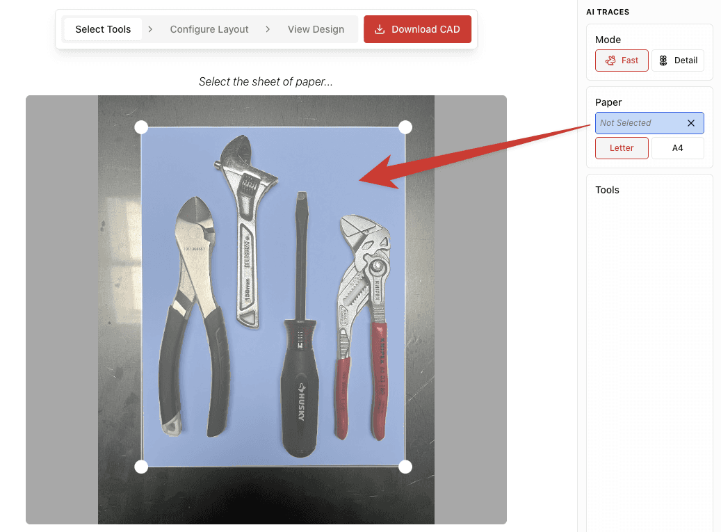
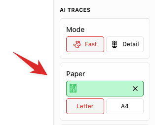
Paper Selection
Selecting the paper correctly is critical for accurate scaling. This is the most common source of sizing issues.
Paper Size Settings
Make sure to select the correct paper size that matches what you used in your photo:
LetterUS Standard
8.5" × 11" (215.9 × 279.4 mm)
A4International Standard
210 × 297 mm (8.27" × 11.69")
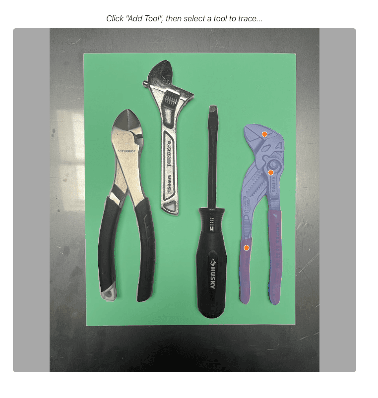
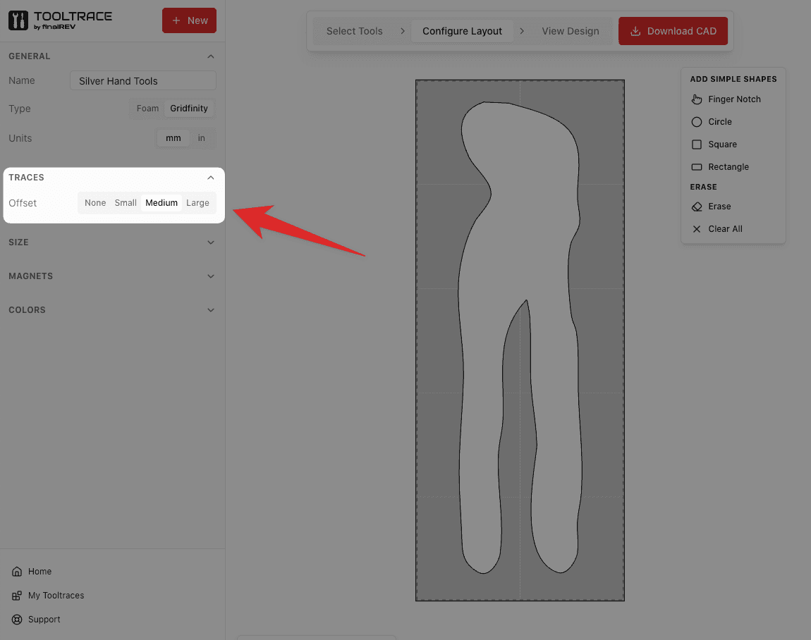
Selecting Tools
After selecting the paper, you can add tools to your design by clicking on them.
Adding a New Tool
Click 'Add Tool'
Click on the Tool
Refine the Selection
Tool-Specific Settings
Each tool has individual settings you can adjust:
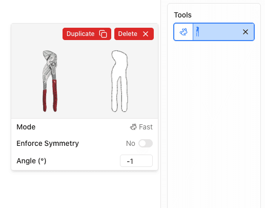
- Duplicate: Create a copy of the tool trace
- Delete: Remove the tool from the design
- Enforce Symmetry: Mirror the outline for symmetrical tools
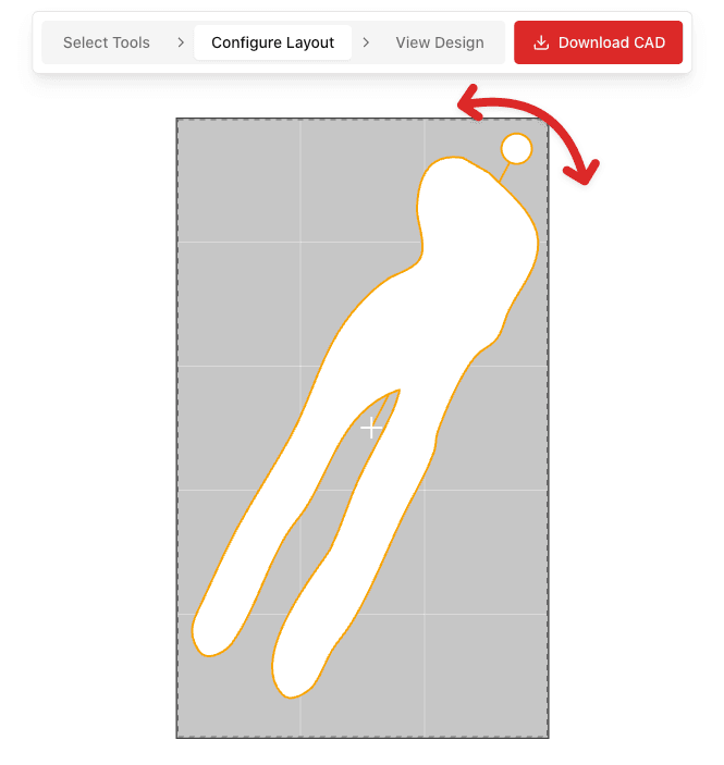
- Angle: Rotate the tool to optimize layout
Settings & Options
Tooltrace offers various settings to customize your design.
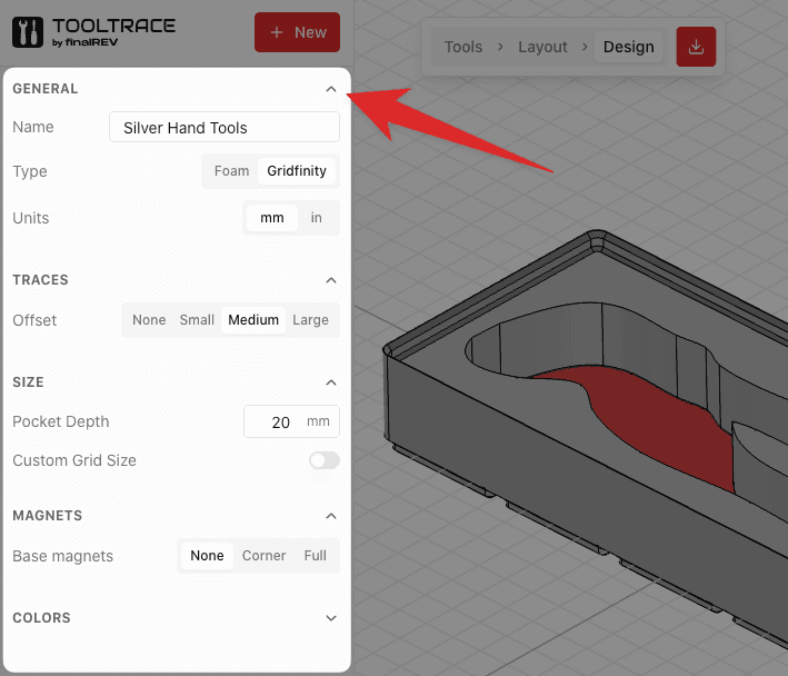
Offset Distance
The offset distance adds clearance around your tool outline, making it easier to insert and remove tools. Choose based on how snug you want the fit:
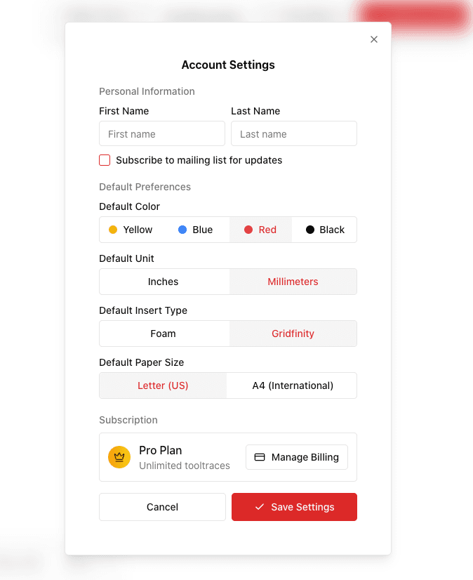
User Preferences
Set your default preferences in the account settings to save time on future projects.
Gridfinity vs Foam
Tooltrace supports two types of inserts. Choose based on your manufacturing method and use case.
Gridfinity
3D printable modular storage system with standardized grid sizing.
- Perfect for 3D printing
- Modular and rearrangeable
- Standard 42mm grid units
- Exports: STL, 3MF, STEP
Foam (Kaizen)
Traditional shadowbox foam for CNC cutting or manual cutting.
- Custom dimensions
- Fits any drawer/case
- Laser/CNC compatible
- Exports: DXF, SVG, STEP
Pro Features
Tooltrace Pro unlocks advanced features for power users. Free users can use these features in their designs but will need to upgrade to export the final CAD file.
Detail Mode
Enhanced AI processing that captures finer details in complex tool shapes. Takes up to 1 minute per tool but produces highly accurate outlines for intricate tools. Free users get a limited number of traces to try it out.
Custom Shapes
Draw circles, squares, and rectangles directly on your design. Perfect for adding storage spots for batteries, screws, or other small items that don't need AI tracing.
Import Tools
Reuse traced tools from your other tooltraces. Great for standardizing tool storage across multiple inserts without re-tracing the same tools.
Magnet Holes
Add magnet holes to Gridfinity inserts for secure baseplate attachment. Configure pattern, diameter, and depth to match your magnets.
Custom Sizes
Customize finger hole diameter (default 20mm) and Gridfinity grid cell size (default 42mm) to match your specific needs or non-standard setups.
Exporting Files
Tooltrace supports multiple export formats for different manufacturing methods.
Universal 3D printing format. Works with all slicers (PrusaSlicer, Cura, Bambu Studio).
Includes color and metadata. Recommended for modern slicers.
Solid model format for CAD software and professional CNC machining.
2D outline for laser cutters, CNC routers, and vinyl cutters.
Vector format for hobbyist cutters like Cricut, Glowforge, and design software.
Print-at-100% paper template for confirming your outlines fit before you commit to a 3D print or CNC cut. Strongly recommended before placing a print order — see the next section.
Size-Check PDF
The size-check PDF is a one-page-per-tool printable template that lets you verify your tooltraces are the correct real-world size before you 3D print, CNC cut, or place a print order. It's the cheapest, fastest way to catch sizing mistakes — saving you wasted filament, money, and time.
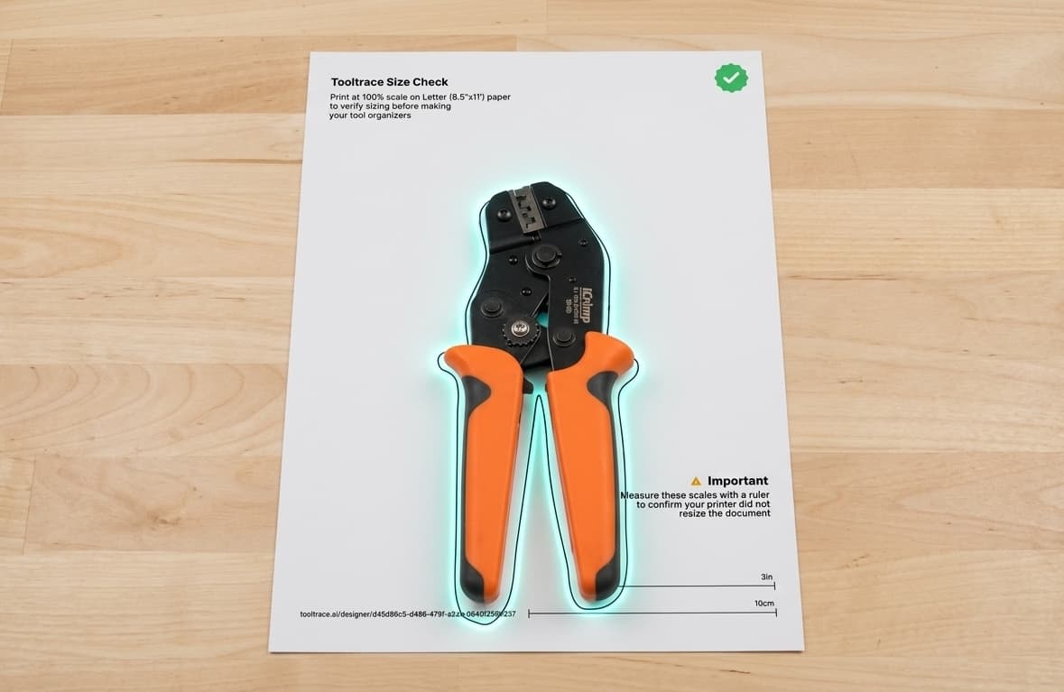
What's on the page
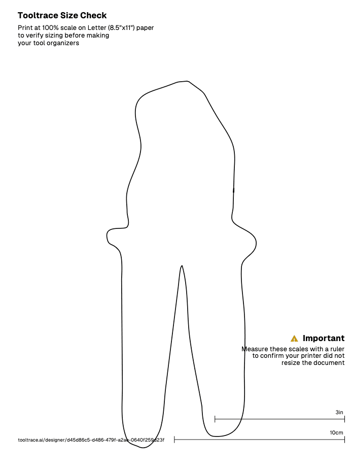
- Outline at 1:1 scale — the exact shape Tooltrace will pocket out of your tray, drawn at real-world size.
- Calibration rulers — a 3-inch and a 10-cm reference line in the bottom corner. Measure them with a real ruler to confirm your printer didn't apply “Fit to page” or other scaling.
- Project link — a short URL back to your design so you can pick up where you left off.
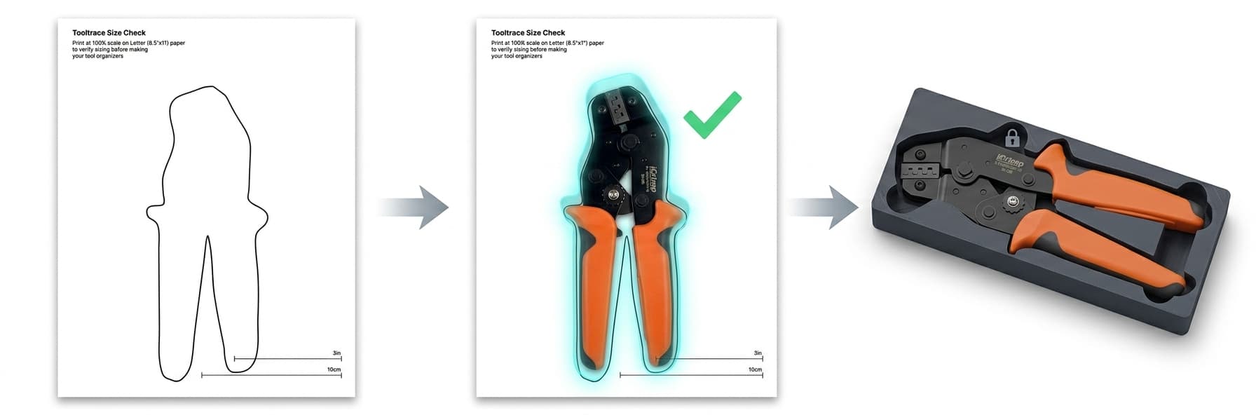
How to use it
Download the PDF
Print at 100% scale
Verify the printer didn't rescale
Drop your real tools onto the outlines
Community
The Tooltrace Community is a free library of ready-to-use tool inserts shared by other users. Browse, download, customize, and publish your own designs.
Browsing & Downloading
Browse the Library
Preview a Listing
Download Files
Customizing a Design
Every community listing has a "Customize This Design" button. Clicking it creates a personal copy in your designer where you can:
- Reposition, rotate, or remove tools
- Change offset distance, thickness, and panel size
- Add new tools from your own photos
- Switch between Gridfinity and Foam modes
Your edits are saved as a separate design — the original listing is never affected.
Publishing Your Own Design
Finish Your Design
Click Publish
Add Details
Submit for Review
Ratings & Tool Cards
After downloading a design, you can rate it on three dimensions to help others in the community:
Accuracy
How closely the insert matches the actual tool dimensions.
Ergonomics
How easy it is to insert and remove the tool from the holder.
Rarity
How hard to find or unique this particular tool insert is.
Each listing also gets a collectible Tool Trading Card that displays its stats, grade, and seller badges. You can view and download these from the "Tool Card" tab on any listing.
Troubleshooting
Solutions to common issues.
CAD Export Geometry Errors
Sometimes exports fail due to geometry issues—shapes overlapping or intersecting in ways that create invalid 3D geometry. Here are the most common causes and how to fix them.
Common Causes
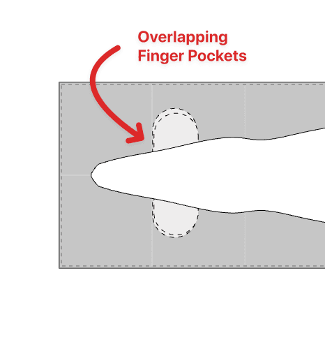
Two or more finger pockets are intersecting each other.
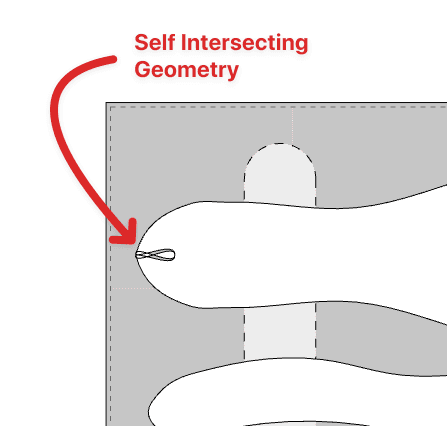
A tool outline crosses over itself creating invalid geometry.
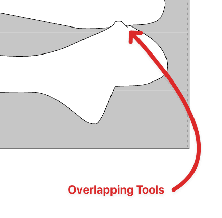
Tool outlines are overlapping or touching each other.
How to Fix
Pro Tips
Use Colored Paper
Green, blue, or orange paper provides great contrast for most tools.
Keyboard Shortcuts
Press N or Enter to quickly add a new tool without clicking the button.
Duplicate Tools
Have multiple identical tools? Trace once and duplicate to save time.
Rotate for Efficiency
Rotate tools to pack them more tightly and reduce material waste.
Auto-Save
Your work is automatically saved. Come back anytime from 'My Library'.
Test Fit First
Print a single layer test or use cardboard to verify fit before full production.
Frequently Asked Questions
Still have questions?
We're here to help! Reach out and we'll get back to you as soon as possible.